This is an old revision of the document!
Lenovo T530 Laptop Wi-Fi upgrade
BIOS Version: G4ET62WW (2.04 )
Current Network card: Intel Corporation Centrino Wireless-N 2200 [8086:0891]
I successfully installed an Intel Dual Band Wireless-AC 7260 wireless card by modifying the whitelist in the BIOS. I've compiled this step-by-step guide with references as I had trouble finding a similar resource online.
New Network card ID: Dual Band Wireless-AC 7260
- Bluetooth: [8087:07DC]
- Wi-Fi: [8086:08B1], Secondary: [8086:4070]
IBM COMPATIBLE 486 BIOS COPYRIGHT Phoenix Technologies, Ltd Phoenix BIOS SC-T v2.2


- MX25L6406E (8MB)
- MX25L3206E (4MB) (Under frame) (This is the BIOS chip I need to flash)
- There is another EEPROM on the underside of the bios which contains the bios passwords which I am not going to touch.
Required components
- Your Thinkpad laptop (of course)
- New PCI-E Network card (Approx. $20 from eBay or Aliexpress)
- A second computer (I used another Linux computer. A Windows computer can work, but I haven't tried it)
- A high quality (small) Phillips screwdriver, all of the screws in the laptop are Phillips, and you don't want to accidentally strip any screws.
- Hex driver for the studs on the SVGA connector
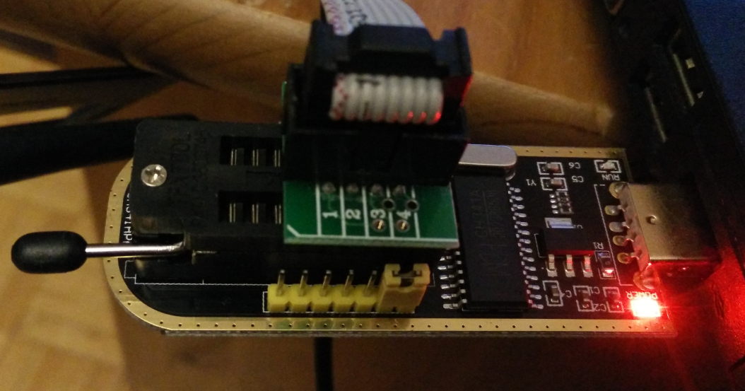
- CH341A programmer (Approx. $3 from eBay or Aliexpress)
- SOIC8 Test clip (Approx. $4 from eBay or Aliexpress)
Steps
Take plenty of photos as you disassemble your laptop, including cable routing, as well as which screws came from where. Also, Take your time, don't rush
- Determine current wireless card VID:PID via Linux: lspci -nn
- Download Flashrom
- Download UEFITool
- Following the Hardware manual, disassemble the laptop to access the system board.
- Place the system on a non-conductive surface (As you will be powering up a portion via the CH341A programmer.
- Pin 1 of the test clip is the wire with the Red stripe, which goes towards the corner of the memory chip with the circle.
- I was fortunate enough to have a similar memory chip from another device I was able to use to test the programmer connections ahead of time.
- Connect the test clip to the programmer, (Facing downwards, in the top half of the ZIF socket)
- Read the existing BIOS
- flashrom -p ch341a_spi -c “MX25L3206E/MX25L3208E” -r ORIGINALBIOS.ROM
- Read multiple times to verify the data is correct. (Compare via MD5SUM)
- Note: If you are getting errors, or inconsistant data, try adjusting the test clip slightly.
- IMPORTANT: Make a copy of the original bios, or email it to yourself so you don't accidentally lose it.
- Modify bios
- Linux: cp ORIGINALBIOS.ROM MODIFIEDBIOS.ROM
- Open firmware (MODIFIEDBIOS.ROM) in UEFItool (Works well under wine)
- File > Search, Select GUID, search for 79E0EDD7-9D1D-4F41-AE1A-F896169E5216 (LenovoWMAPolicy)
- GUID pattern “79E0EDD7-9D1D-4F41-AE1A-F896169E5216” found as “D7EDE0791D9D414FAE1AF896169E5216” in 79E0EDD7-9D1D-4F41-AE1A-F896169E5216 at header-offset 0h
- Go to PE32 Image section, right click, “Extract as is”
- Save as LenovoWmaPolicyDxe_orig.sct
- Linux: cp LenovoWmaPolicyDxe_orig.sct LenovoWmaPolicyDxe_mod.sct
- Using a hex editor, search for whitelist
- Linux: hexedit LenovoWmaPolicyDxe_mod.sct
- /(to search), EC10<enter> (I've chosen to modify the 10EC Vender device)
- Change EC10 to 8680 (New device is 8086:08B1)
- Change 7681 to B108
- Change EC10 to 8680 (Secondary VID:PID is 8086:4070)
- Change 9581 to 7040
- Change 9517 to 8780 (Bluetooth VID:PID is 8087:4070)
- Change 2007 to DC07
- Ctrl-x (To save & exit)
- Back in UEFITool
- Right click on the same PE32 Image section again, select “Replace as is”
- File > Save Image file, save as MODIFIEDBIOS.ROM
- Flash new bios
- flashrom -p ch341a_spi -c “MX25L3206E/MX25L3208E” -w MODIFIEDBIOS.ROM
- (It did take a couple attempts, and as I mentioned earlier, I did try fiddling with the test clip to ensure it was properly seated.
- Verify bios:
- flashrom -p ch341a_spi -c “MX25L3206E/MX25L3208E” -v MODIFIEDBIOS.ROM
- Reassemble laptop to the point of booting
- basically, everything up to the trim, keyboard, and display.
- I used the existing thermal compound for testing, then I cleaned it off to apply new thermal compound prior to final assembly
- Disconnect AC adaptor from wall
- Being careful no loose connectors are reading on the motherboard, I plugged in the disconnected AC adaptor (this way I can apply power without accidentally jostling anything)
- Plug AC adaptor into wall
- Power on via keyboard
- Take note of BIOS message, if you receive an error, take a photo of it.
- Unplug AC adaptor from wall
- Finish reassembling laptop
- At this point I cleaned as I went, cleaning dust out of crevices & such.
- Clean off the existing thermal compound, put new thermal compound on the CPU (and GPU if you have discrete graphics)
- Note: I'm using a separate Bluetooth adaptor, so I'm not concerned about enabling the integrated Bluetooth (Which involves placing kaptop tape over a pin)
Bios from website
- Download matching firmware (Bootable CD) from Lenovo website
- Extract firmware
- geteltorito will extract the bootable disk image from the downloaded ISO Firmware files
Current Whitelist
TODO: Revise list as I made an error in reading to hex file
| Vender:Device | Description |
|---|---|
| 8086:4238 | Centrino(R) Ultimate N 6300 |
| 8086:1111 | |
| 8086:0085 | |
| 8086:1311 | Intel Corporation Centrino Advanced-N 6200 2×2 AGN |
| 10EC:8176 | RTL8188CE 802.11b/g/n WiFi Adapter |
| 10EC:8195 | |
| 10EC:0891 | |
| 10EC:4222 | |
| 14E4:4358 | Broadcom Corporation BCM4322 802.11a/b/g/n Wireless LAN Controller |
| 14E4:0543 | |
| 168C:002B | AR9285 Wireless Network Adapter |
| 17AA:30A1 | |
| 1795:0720 | |
| 1795:0715 | |
| 1795:0022 |
CH341A Programmer
- Supported by flashrom
- flashrom -p ch341a_spi -V
-
- It should be safe to read/flash the chip in situ…
Tested on a similar flash chip
# flashrom -p ch341a_spi -c "MX25L3206E/MX25L3208E" -r T530_BIOS_MX25L3206E -V
flashrom v0.9.9-r1955 on Linux 3.16.0-4-686-pae (i686)
flashrom is free software, get the source code at https://flashrom.org

flashrom was built with GCC 4.9.2, little endian
Command line (7 args): flashrom -p ch341a_spi -c MX25L3206E/MX25L3208E -r T530_BIOS_MX25L3206E -V
Calibrating delay loop... OS timer resolution is 2 usecs, 745M loops per second, 10 myus = 12 us, 100 myus = 101 us, 1000 myus = 1006 us, 10000 myus = 9992 us, 8 myus = 10 us, OK.
Initializing ch341a_spi programmer
Device revision is 3.0.4
The following protocols are supported: SPI.
Probing for Macronix MX25L3206E/MX25L3208E, 4096 kB: probe_spi_rdid_generic: id1 0xc2, id2 0x2016
Found Macronix flash chip "MX25L3206E/MX25L3208E" (4096 kB, SPI) on ch341a_spi.
Chip status register is 0x00.
Chip status register: Status Register Write Disable (SRWD, SRP, ...) is not set
Chip status register: Bit 6 is not set
Chip status register: Block Protect 3 (BP3) is not set
Chip status register: Block Protect 2 (BP2) is not set
Chip status register: Block Protect 1 (BP1) is not set
Chip status register: Block Protect 0 (BP0) is not set
Chip status register: Write Enable Latch (WEL) is not set
Chip status register: Write In Progress (WIP/BUSY) is not set
This chip may contain one-time programmable memory. flashrom cannot read
and may never be able to write it, hence it may not be able to completely
clone the contents of this chip (see man page for details).
Reading flash... done.
Coreboot project
BIOS Files
- xxx.PAT are CPU Microcode files
- xxx.hsh are CPU Microcode hash files
- something.FL1 the actual BIOS image.
- There's also .FL2, that's the Embedded controller1)
Reference
-
-
- GUID: 79E0EDD7-9D1D-4F41-AE1A-F896169E5216_2207
-
- Other BIOS mods
- Other
Screen
Currently: 15.6“, 16×9, 1366×768
| FRU | Description | Resolution |
|---|---|---|
| 04W3339 | LCD 15.6”HD AG | WXGA (1366×768) |
| 04W3345 | BOE 15.6“HD AG | WXGA (1366×768) |
http://replacethinkpadscreen.blogspot.ca/2013/01/replacing-t530s-screen.html
Possible replacement: B156HW01 V.4